Involute Curve Generation with Pro/Engineer (Creo)
Involute curves got wide range of Mechanical Engineering applications like Involute Gear Teeth, Centrifugal casing design, etc. Let us see how to create an involute curves in Pro/Engineer (Creo).
Equation of Involute curve (Parametric, Cartesian Coordinate)

Here are the steps to create an Involute Curve using the above equations in Pro/Engineer
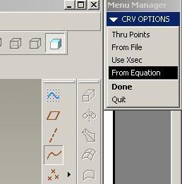
1. Create a datum curve using the option ‘From Equation’
Insert -> Model Datum -> Curve -> From Equation2. Select a Coordinate System
3. Select Cartesian as Coordinate System Type
4. Input the following equations in the popup textpad
a = 100
Theta = T * 360 * 2    /* for 720 degree involute
x = a * (cos (Theta) + (PI  * Theta / 180) * sin (Theta))
y = a * (sin (Theta) - (PI  * Theta / 180) * cos (Theta))
z = 0
Where 'T' is a Pro/Engineer system variable, and its value will vary from 0 to 1 during the execution of the program. You can control the angle of involute by changing value multiplication value after 'T'.
For example if you want to create an involute curve from 30° to 70°, just modify the equation of Theta to
Theta = (T*(70-30))+30
Also note that in Pro/Engineer you need to enter angle in degrees instead of radian to compute cos & sin.
5. Save the File and close it. And Give Ok.
Check your curve with the figure below.(Blue colour circle is the base circle)
Labels: CAD, Computer Aided, feature, ProEngineer


